


|
|
|
|
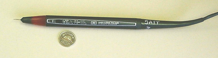
Introduction to the tool: The logic pulser HP 546A is a digital tool that is used in troubleshooting circuits.It use the technique of injecting a controlled pulses into the circuit under test.The pulse amplitude is dependent on the logic supply voltage.The logic pulser is compatible with CMOS and TTL and its pulses will override the current state of the circuit ,this mean that the logic pulser will drive a high logic level to low and a low logic level to high.The frequency and number of pulses generated by the pulser can be programmed or controlled by a push-slide button that is situated close to the tip of the logic pulser.The pulser operates in three states High ,low and off . In the off state the pulse has no effect on the circuit under test because of the high impadence of the pulser. The logic pulser has a mode switch .This swich can set the pulser to operate in TTL or CMOS mode. Figure#1:the logic pulser.
The 546A logic pulser generates pulses as programmed by a push-slide button that is situated close to the tip of the tool.The pulse can produced by pushing the button once for each single pulse output ,or a specific number of times for a continues pulses stream or pulse burst at a selected frequencies.The following table shows the output frequencies as a function of the number of bushes.
The logic pulser power supply depend on the circuit under test. When a CMOS circuit is tested the power leads of the logic pulser should be connected to a 3-18v DC voltage source and when a TTL circuit is tested the power leads of the logic pulser should be connected to a 4.5-15v Dc volt source.
The logic pulser is used mostly with the logic probe to form a powerful tool to detect faults and examine circuits. The logic pulser is used to inject a certain pulse to the circuit and the logic probe is used to detect it .The following is some of the faults that can be detected using the two tools.
|