


|
|
|
|
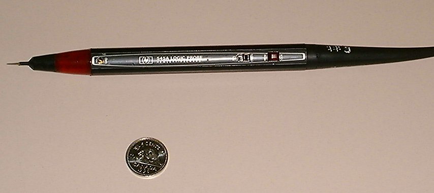
Introduction to the tool : The Hewlett Packard 545A logic probe is an essential tool in the digital electronic field .It is used to detect and indicate High or Low logic levels .In addition The probe also can indicate the intermediate or "bad" logic level,including the open nodes on TTL or CMOS circuits.The presence and polarity of a single pulse >= 10 sec or a pulse train up to 40MHz CMOS or 80MHz TTL will be detected by the probe.The probe use a simple lamp to indicate the logic levels of the circuit.The probe is compatible with different kind of chips like TTL ,DTL ,HTL ,MOS CMOS and HINIL integrated circuits. The logic probe has many features .The most important one is the memory indicator lamp, which is located under the MEM_CLR button.This indicator lamp turn on when :
The memory indicator remains on until the MEM_CLR button is pressed .The probe has also a mode switch that can be used to toggles the probe to operate in either TTL or CMOS modes.In the TTL mode the probe should be powered by a voltage supply of 4.5-15v DC ,while in the CMOS mode the probe should be powered by a voltage supply of 3-18v DC. Figure #1 shows the logic probe .
Logic lamp indications: The logic lamp is located in the tip of the probe and would give an immediate indication of the logic status of the circuit under test.the logic lamp can give one of the following indications:
The logic probe is normally is in the dim lamp state.The flashing state indicate that the part of the circuit under test has a frequency .The lamp will flash at around 10Hz. Using the logic probe :
The logic probe can be powered from the supply of the circuit that is under test, or from a regulated DC power supply.If a separated power supply is used the power supply and the circuit under test ground should be connected together.
The logic probe is ideal for detecting short duration's and low repetition rate pulses that would be difficult to observe on an oscilloscope.Positive pulses up to >=10 ns in width trigger the indicatorf or >=50ms ,while negative pulses cause the indicator to go off momentarily.
Several logic circuit analysis techniques use the logic probe to detect the faults .One of these techniques is to run the circuit under test at normal clock rate while monitoring the circuit using the probe for various control signals such as reset ,start shift ,transfer ,or clock signals. Many suspected fault can be detected using the probe which will show the state of the circuit whether it is working as it should be or not. Another useful way is to use the logic pulser to inject the circuit with a slow pulse which allow the changes in the logic signals to occur at a rate that is slow enough to be observed.Then the logic probe could be used to inspect any part of the circuit.
|